Building a CP/M compatible system on perf-board
With a fresh success of building a computer from a kit, I decided to implement an existing design on perfboard, instead of drawing a design of my own right-away for breadboard building. Considering that the RC2014 is closely based on the work of Grant Searle, it was natural for me to take another design of his, and adapt to the 8-slot backplane: the "fully functional CP/M machine using only 9 chips" design.
I broke the design down to separate functional blocks, and built each as a separate card. By splitting the build into these distinct parts, I was able to build one card, and verify functionality of that card using the RC2014 before continuing to the next. All the cards were built on 100mm wide perfboard, using a direct soldered wire approach.
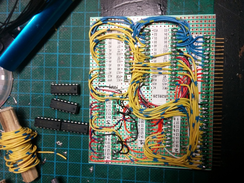
- RAM/ROM card
- SIO/2 serial IO card
- 8-bit IDE adapter for CF card
- CPU board with onboard Clock and Reset
- YM2149F sound card
I chose to make the RAM/ROM as a single combined card, because I did not want to split the ROM-disable function needed for CP/M up across two cards. It also allowed me to reduce the potential part count (by 1 IC). Because of the close relationship between the RC2014 design and the one I was implementing, I could simply use the ROM content from the RC2014 for verifying the ROM/RAM using the CPU and Serial I/O board from the kit.
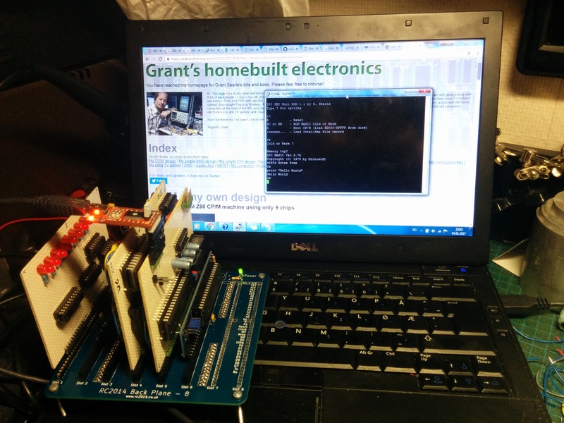
Grant's CP/M design uses a different UART from the BASIC design. The BASIC design uses a 65B50, while the CP/M design uses a SIO/2. So this was the next card to be built. To verify this one, I burned a new ROM containing the "monitor" for the complete CP/M-design. This monitor also includes an 8k BASIC version, so it was easy to verify the SIO/2 board without having a CF-storage approach available.
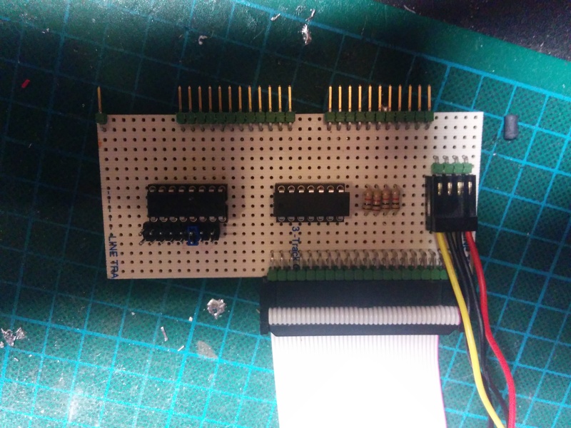
The original breadboard design page talks a bit about how to wire up a Compact Flash card, and how to hand-solder the SMD connector used for CF-cards. I did really not want to deal with that connector directly, and gambled on being able to use an IDE-to-CF adapter, considering the design really uses CF in 8-bit IDE mode anyway. My "IDE adapter" is basically a couple of OR-gates, an '138 address decoder, some resistors and a 40-pin male header connector. And it worked! With a short IDE cable between my "adapter" and a commercial IDECF-adapter, I was able to prep the CF card, load software onto it, and boot to a lovely "A>" prompt!
I could have rested here, but decided to whip up a new CPU board, as that, plus the clock generator, now was the only cards from the RC2014 kit that was in use. I integrated the clock, and also added an auto-reset onto the CPU card.
With these cards on the backplane, I now had a working Z80 based system, that I had needed to do some desgin-work for myself to adapt it to multiple cards. It was even a working CP/M system, with bonus ROM-based BASIC. To further verify that I did indeed have a CP/M compatible system, I grabbed a copy of Zork 1, I think it was from http://www.retroarchive.org/cpm/games/games.htm, and loaded it onto the CF-card using Grant's DOWNLOAD.COM utility. I believe any fully CP/M compatible system should have a copy of Zork 1 on it. And mine does, and it works 😀 I have used Zork as a demonstration of the system so much now, that my friends and colleagues have started to call my homebrew CP/M computers "the Zork machines" 😀
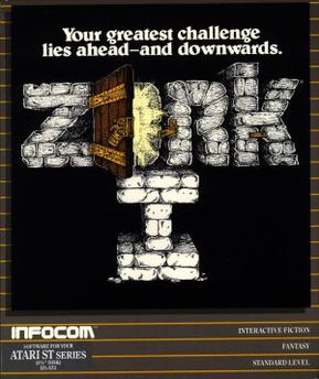
Zork I box art
The final card I built for the RC2014 bus, was a YM2149F synthesizer sound chip adapter. It required some fairly weird address decoding logic, so I spent quite a while on the design of this relatively simple card. After laying it out on perfboard and soldering up the wiring, I had a working sound card. I do believe I am starting to get a hang of this... What I still don't have as good a hang of, is large-scale assembly projects. So, I have tested the YM-card extensively from BASIC, and I have some general test-routines for it written in Assembly. But I have not made any proper songs using it, and I am quite far from implementing a Tracker or Player of any kind.
What I have used the system for, however, is getting to know how to code z80 Assembly for CP/M. It's a neat little operating system. A task as "small" as reading a file from disk has you digging quite deep into the system itself. As a result you end up with a very deep understanding of how the operating system internals work. And being such a small operating system, it is quite possible for a person to understand the entire operating system, after a reasonably short time studying it.
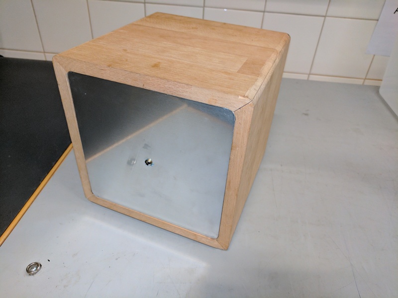
I created a final board for the system. By using a very cheap Chinese strip-board, I created a barebones version of the backplane. This freed up the RC2014 backplane to go back to being used with the original kit, and also made the computer a completely homebrew build. After this, the electronics part of the perfboard project was done. With such great results on the electronics side, I figured it deserved a nice place to live, and not become yet another stack of project parts in one of my bins of such. So I built a wooden cabinet for it, with some 3D printed parts to hold the cards in place. The case is made from beech wood, with an inlaid aluminium front.
This post is part of a series documenting my journey in making my own homebrew computer, the posts can be found on this link.
