My first working homebrew was a kit: RC2014
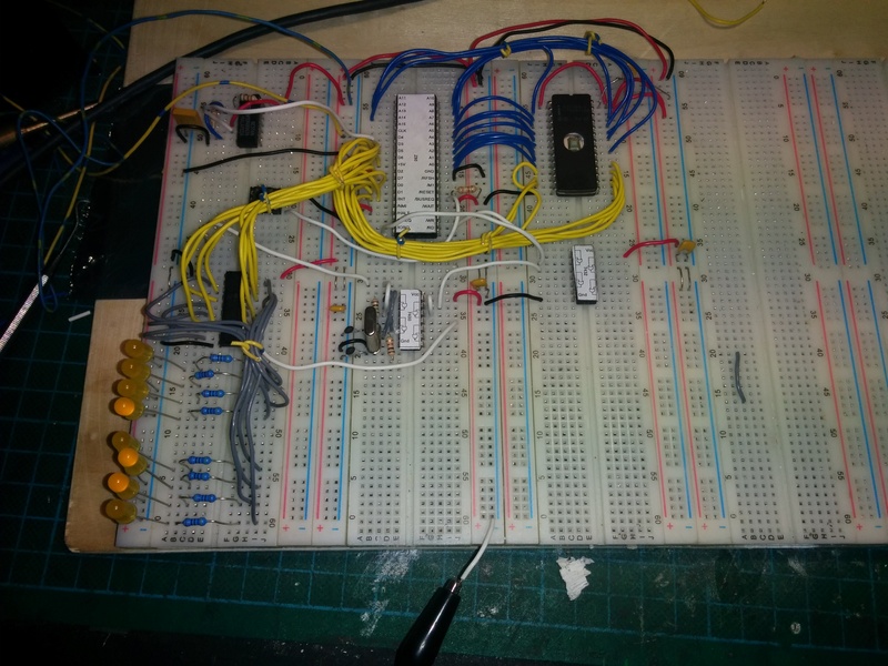
After having solved the mystery of counterfeit parts, I felt ready to start attacking my master plan of building my own Z80 based computer. I wired up a CPU test circuit and used with great success. I then wired up a simple system on a set of cheap breadboards, consisting of the CPU, a ROM chip and a slow clock generator. With LEDs on the address bus, I punched up some simple assembly that NOP'ed for a while, did a JMP, NOP'ed some more, and then JMP'ed back to start. This was assembled using TASM under Dosbox, and loaded into the ROM using my Minipro programmer. When I applied power to the circuit, it started ticking along, and did just what I expected it to do!
Success! With great spirit, I next wired up a far more "complex" circuit. I added a few support logic gates, a 74LS138 4-to-8 decoder and a 74LS373 8-bit latch, and moved the LEDs from the address bus to the outputs of the latch. With the added components, I had a kind-of 8-bit digital output. With a simple counter code typed and assembled, I had partial success. The circuit and code worked. And then sometimes it didn't. And sometimes when it didn't work, it would start working after some time.
With the bad experiences from fake chips, I started suspecting that my cheap breadboards were causing problems. So I moved the circuit over to one of my "known good" breadboards, part of an old digital trainer device. Now the circuit and code worked most of the time, but still sometimes not. I was getting frustrated. I tore down my wiring, checked and verified my circuit, wired it back up, and got the same result. Was there something that I had completely misunderstood? Was there something very wrong with my method?
Eventually, I decided to stop faffing about. I decided that the best way forward, would be to start building a known good design. With that, I would be able to verify that I am able to pull this off, and I would be able to use it to test and verify what I was designing from scratch. So, enter the RC2014!
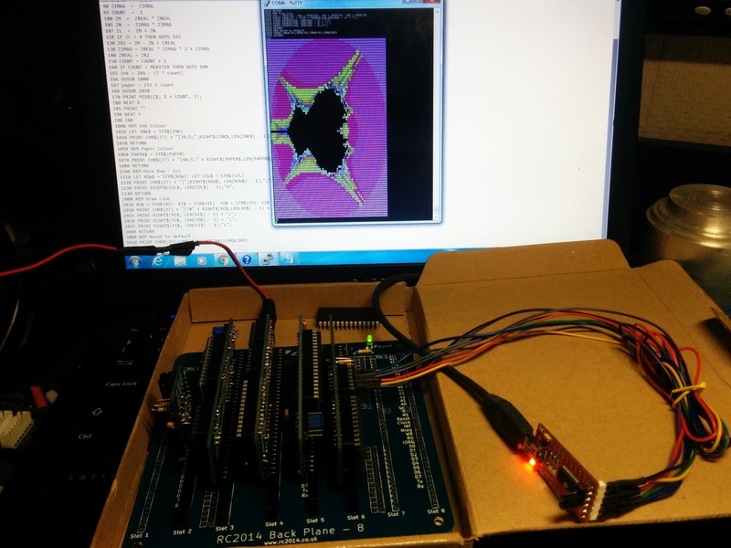
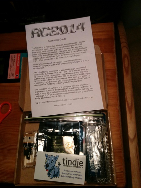
It was now late december 2015, perfect timing for a "christmas gift to self" kind of a purchase. In my research for options and ideas, I had looked at Spencer Owen's RC2014 several times. It is a dead simple design, and cheap as well. Perfect match. Off to Tindie I went, my order placed on saturday the 19. december. I was very impressed when the kit arrived in my mailbox on the 23rd! I brought the kit with my on my Christmas holiday, and by the 27th it was completed. I connected up a TTL-USB adapter, and powered the thing up. To much joy, the kit sprung to life! Grant Searle's BASIC monitor greeted me with Microsoft BASIC for Nascom (modified by Searle and Owen).
This was back when the only RC2014 kit available was the "Classic" version. My kit was the "Full monty" set, with all components, and the 8-slot backplane. The kit was genuinely well put together. The PCB's are simple, but cleanly presented. Components were well packaged, and sorted. The instructions were simple, but clear and concise. The overall packaging was small! As for ease-of-build, there are many connections to solder, and get right in a kit of this type, so I would not recommend it to a beginner. But even with the simple pen-style soldering iron I keep at mum's home, I was able to complete the job cleanly in a reasonable amount of time. So I'd call it an intermediate kit easily. I can happily recommend Spencer's kits, and the new, updated versions of RC2014 kits look nice indeed. I'm tempted to buy another one, to be honest 🙂
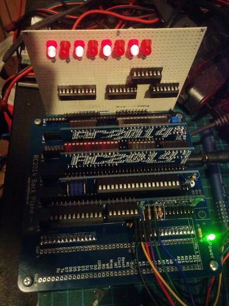
I now had my first working Z80 based homebrew computer! And with an 8-slot backplane, I had 3 slots available, as the original kit uses 5 slots: CPU, ROM, RAM, Serial I/O and Clock generator. With a simple bus format using Single row connectors, it should be easy to make expansion cards. I dug out a perf-board, added the needed right-angle single-row header pins, and soldered up the exact circuit I had tried on my breadboard. I plugged it into the backplane, and tested it using OUT statements in BASIC. It worked! Another great success, but at the same time somewhat of a mystery to me. Why did it not work on breadboard, when it worked fine in a more complex system? I decided to test removing the RAM and Serial cards, and load my test-ROM onto the ROM card. Suddenly, the I/O board was behaving erratically again. Thanks to RC2014, I now had proof that my hardware was working, and my software was bad. The kit had actually already accomplished what I wanted: verify that I could assemble a working system from someone else's design, and verify that I could design working hardware myself.
All of this made me make a change of plans. Instead of going back to the breadboard, I decided to try to implement Grant Searle's Minimal CP/M system using home-built cards for the RC2014 backplane, before proceeding with my own design. The process of this is the topic of a post of it's own.
I have since (much later, really) dug out the wonky test-code, and corrected my mistakes. I can't remember what exactly was wrong, but I seem to remember it was embarrassing. I have not tried wiring it up on breadboard again, as all my Z80 CPUs have been busy running on other systems 🙂
This post is part of a series documenting my journey in making my own homebrew computer, the posts can be found on this link.


