Flaws in my simplified CoreXY idea
After building my first prototype of a CoreXY based cartesian movement system, as shown in two earlier posts ((CoreXY Experimentation))((CoreXY experimentation update)), I have realized that my idea for a simpler pulley configuration is flawed. I've simply forgot basic geometry math. The idea was to start with a CoreXY system, as described on http://corexy.com, take inspiration from FABtotum to avoid crossing belts, and simplify the pulley location to get as few anchor poins for the belts as possible. My attempt used two "layers" of belt paths, and tried to reduce the number of pulley-axles to 4, compared to CoreXY's 8 and FABtotum's 6. But, unless I start offsetting the location of stepper motors (and introducing uneven stress on the frame), I end up with an undesired geometry...
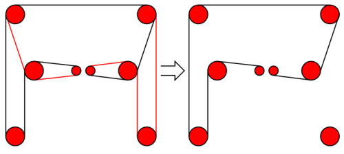
The belt path as I've designed it looks something like the following figure, where black and red lines represent two separate belt paths (note, the path is identical on the "top" part..).

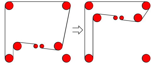
That's the belt path simplified down to one side. Let's see what happens to that side when we move our gantry on the Y axis, and by that I mean moving the "crossbar of the H shape up and/or down". That part of the belt path that isn't a straight line but rather askew in the drawing starts doing wonky stuff...

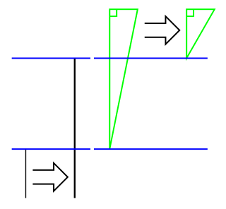
This should have been obvious to me before I started the experiment, but sadly it wasn't. If you can't see what is going on, let's simplify the drawing so we only look at the bits of the belt path that changes:

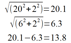
The black lines indicate the lengths on the "straight side", the change here is identical to the distance between the blue lines. If we started with a long side of 20, and ended at a short side of 6, the distance between the blue lines will be 14. Let's call that delta A. The green triangles however, show that changing distances on the other side effectively creates two different right-angled triangles, where one of the right-angle legs side stays unchanged (defined by the diameter of the pulleys) at, let's say 2, while the other changes by the same amount as delta A. The actual belt path, however has changed by the change in the hypotenuse! So we need to calculate both hypotenuses to get the delta:

So the change in the side of the triangle is 0.2 smaller than on the straight side! Ok, that may not be a large number. But remember, the intention is to build a precise cartesian machine like a plotter, CNC or 3D printer. Where we need exact moves in tens-microns increments. The numbers used here are also examples. In reality the gantry is going to be covering some 30 centimeters, and we'll end up with a delta of close to half a centimeter!
That's NOT going to go down well in terms of belt tension and positional stability.
An eagle-eyed reader will notice that I have triangles also on the X part of the cartesian plane. Those triangles do not pose problems. as they are symmetrical on the two sides of the carriage, so the belt paths change symmetrically. However, the advantage of CoreXY on the X-axis is lost on the Y-axis when not using spaced out anchor points.
Next up, I'm going to use a conventional CoreXY setup. Yeah, let's try not reinventing the wheel 🙂
March 6th, 2015 - 00:40
Hi, I saw all your videos, they are great. First, you had two corners with idler pulleys stacked on the same screw. Later, it seems you switched to separate screws for each idler pulley. Why did you need to separate them? I guess you didn’t get enough rigidity. I am asking because I plan to do the same (stack the pulleys).
Best regards!
November 14th, 2015 - 15:55
Well, the reason why I’m no longer using that arrangement is basically the topic of this post, so I hope I’m not being rude if I ask you to please read the post again…
August 16th, 2015 - 10:32
Appreciating the hard work you put into your site and in depth information you present. It’s nice to come across a blog every once in a while that isn’t the same old rehashed information. Great read! I’ve saved your site and I’m adding your RSS feeds to my Google account.